



Polymer melt candle filters support stable melt cleanliness, controlled pressure development and protection of downstream equipment. Applications include PET, rPET, PA6, PA66, PP and speciality polymers. Media type, filtration rating, geometry and connection are selected to suit the polymer, contamination, throughput and pressure profile.
Engineered Filtration for High Viscosity Polymer Processing
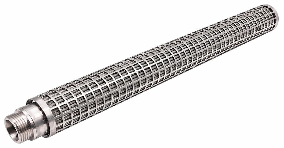
Melt Cleanliness and Process Stability
Candle elements remove hard particles and deformable contaminants from high viscosity polymer streams before downstream processing. Typical contaminants include carbonised particles, metal oxides, agglomerates, undissolved polymer and gels. Controlled retention can reduce contamination related defects, filament breaks and production interruptions. All metal construction is used for fibre, film, resin and other high temperature services.
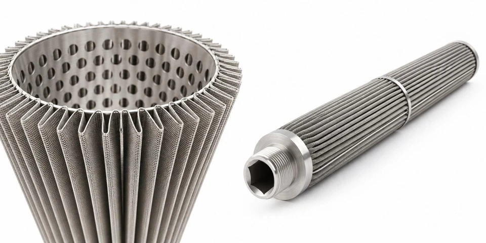
Element Construction
Supported pleated media increases effective filtration area, while welded supports maintain the flow path under pressure and through qualified cleaning cycles. All metal construction avoids fibre or binder shedding from nonmetallic filtration layers.
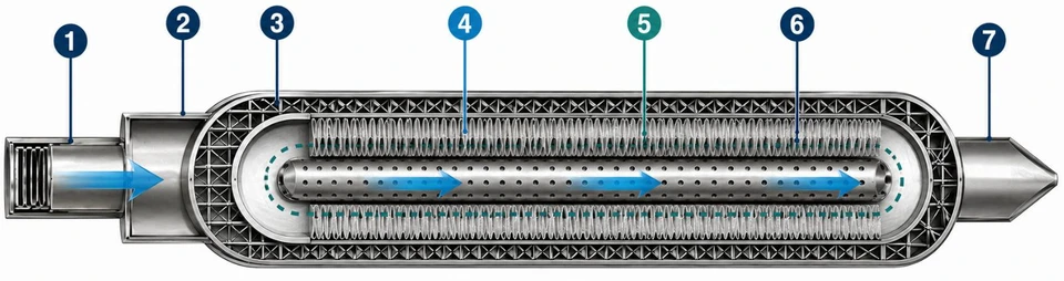
Filtration Media Selection
Defined openings for surface filtration.
Three dimensional pores for depth filtration.
Filtration and drainage layers with structural support.
Woven Stainless Steel Mesh
- Retention Mechanism
- Predominantly surface filtration through defined woven openings.
- Typical Duty
- Hard particles, lower contaminant loading and coarser filtration.
- Selection Considerations
- Good permeability, narrow pore distribution and comparatively straightforward cleaning.
Sintered Stainless Steel Fibre
- Retention Mechanism
- Depth filtration through a bonded three dimensional porous fibre network.
- Typical Duty
- Hard particles and deformable gel contamination.
- Selection Considerations
- High porosity and dirt holding capacity; resistance to temperature, differential pressure and repeated cleaning.
Supported Composite Construction
- Retention Mechanism
- Application specific filtration, drainage and structural layers.
- Typical Duty
- Duties requiring a balance of gel control, strength and permeability.
- Selection Considerations
- Supports pleat stability and distributes flow through the available area.
Select the coarsest rating that achieves the required melt cleanliness and product quality with an acceptable initial pressure drop and service life. A micron rating alone does not describe the complete retention performance.
Supporting Filament and Product Quality
Linear Density / Decitex / Denier
- Potential Filtration Contribution
- Reduced filament to filament and along length variation by limiting capillary restriction and unstable contaminant passage.
- Other Important Factors
- Average linear density is set by actual mass flow and take up speed.
Tenacity
- Potential Filtration Contribution
- Fewer contaminant weak points and more consistent minimum strength and tenacity CV.
- Other Important Factors
- Mean tenacity depends on polymer molecular weight, orientation and drawing.
Elongation
- Potential Filtration Contribution
- More uniform filament formation and drawing may narrow the distribution.
- Other Important Factors
- Changes in mean elongation remain process dependent.
Evenness / Uster CV%
- Potential Filtration Contribution
- Fewer transient restrictions, partial blockages and contamination events may reduce thick and thin variation.
- Other Important Factors
- Pump, quench and winding stability remain important.
Shrinkage and Dye Uptake
- Potential Filtration Contribution
- Uniform formation can support consistent orientation, shrinkage and dye response.
- Other Important Factors
- Thermal history and drawing remain decisive.
Defects and Line Stability
- Potential Filtration Contribution
- Fewer gels, slubs, broken filaments, spin breaks, fuzz and interruptions.
- Other Important Factors
- An overly fine or overloaded element can cause excessive pressure and short life.
Stable total linear density with poor single filament uniformity can indicate local flow distribution, contamination or capillary restrictions rather than a metering setpoint problem.
Representative Operating Values
The following indicative figures vary with the manufacturer and element construction. The approved quotation, drawing and element datasheet must establish the limits for the supplied construction.
Working Pressure and Differential Pressure
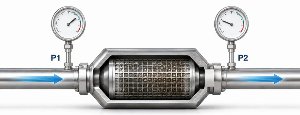
Working pressure is the line or housing pressure. Differential pressure is the upstream pressure minus the downstream pressure across the element: ΔP = P1 − P2. Differential pressure determines the element loading and must remain within its certified structural and terminal operating limits.
Record the clean pressure drop at stabilised throughput, temperature and viscosity as the operating baseline. Compare subsequent readings under equivalent conditions.
Typical Polymer Applications
PET & RPET Fibre
- Typical Contamination
- Carbonised polymer, gels, oxides and recycled feed variability.
- Selection Focus
- Gel retention, controlled pressure rise and stable service life.
PA6 / PA66 Filament
- Typical Contamination
- Thermal sensitivity, gels and hard particles.
- Selection Focus
- Low residence volume, compatible alloy and controlled differential pressure.
PP Fibre & Nonwovens
- Typical Contamination
- Additive agglomerates, char and solids.
- Selection Focus
- Rating, throughput per element and cleanability.
Film & Resin Finishing
- Typical Contamination
- Visible defects, gels and appearance related contamination.
- Selection Focus
- Fine retention, uniform flow and integrity verification.
Connections and Dimensional Control
Connection names are only a starting point. Sealing details, insertion length, flow direction and removal features must match an approved housing drawing or a verified sample. Quick interface codes are representative and require dimensional confirmation.
Confirm sealing diameter, O ring material, insertion length, flow direction, effective length, outside diameter and the removal feature before manufacture. Photographs alone are not a dimensional specification.
Cleaning and Reuse
The cleaning method must be compatible with the polymer, filtration medium, alloy, welds and contamination. Excessive thermal, chemical or mechanical treatment can damage the element.
Remove bulk polymer using an approved thermal or chemical process, then clean the media and flow path using qualified reverse flow, solvent, chemical or ultrasonic methods. Neutralise, rinse and dry as required. Inspect connections, welds, cage, pleats and dimensions, then verify permeability, clean pressure drop and integrity before release for reuse.
Visual and Dimensional Inspection
Identify pleat or cage damage, weld defects and interface wear.
Permeability / Flow Resistance Test
Confirm adequate removal of retained residue.
Bubble Point
Detect oversized pores, leaks or media breaches.
Cycle History Record
Track cleaning count, pressure recovery and integrity results.
A visually clean element is not sufficient evidence of fitness for reuse. Apply the approved acceptance limits and retain the test history.
Information Required for Selection
Polymer
Grade, virgin or recycled content, additives, intrinsic or melt viscosity and thermal sensitivity.
Process Conditions
Normal and maximum temperature, throughput, element quantity, viscosity and operating cycle.
Contamination
Particles, gels, char, oxides, agglomerates and target defect.
Filtration Requirement
Current and required rating, media type, effective area and quality target.
Pressure Profile
Clean inlet and outlet pressures, initial differential pressure, terminal limit and pressure rise rate.
Housing and Flow
Housing drawing, flow direction, element quantity, spacing, support and dead volume.
Element Dimensions
Overall and effective length, outside diameter, inside diameter or core, end fitting, seals and tolerances.
Cleaning and Life
Cleaning method, cycle count, failure mode, service life and post cleaning testing.
Reference Evidence
Approved drawing, verified sample, photographs, nameplate and existing supplier specification.
Manufacture should be based on an approved drawing or verified sample. Selection balances retention, initial differential pressure, pressure rise, service life and cleaning recovery.
Plant Qualification
Initial Pressure Drop
- What to Record
- Readings at stable throughput, temperature and viscosity after startup.
- Purpose
- Assess permeability and hydraulic fit.
Pressure Rise Rate
- What to Record
- Differential pressure trend over the operating period.
- Purpose
- Assess contaminant loading and service life.
Process Stability
- What to Record
- Throughput, temperature, pressure fluctuations and interruptions.
- Purpose
- Confirm suitability during normal operation.
Filament / Product Quality
- What to Record
- Linear density CV, tenacity and elongation CV, breaks, defects, colour or film appearance.
- Purpose
- Confirm saleable product quality.
Element Condition
- What to Record
- Pleats, cage, welds, seals and retained contamination after removal.
- Purpose
- Assess mechanical suitability and failure modes.
Cleaning Recovery
- What to Record
- Permeability, integrity and differential pressure recovery.
- Purpose
- Assess repeated use suitability and economics.
Agree the drawing, media, rating method, dimensions and design limits before the trial. Define the trial quantity, operating window, monitoring plan and terminal differential pressure, then compare performance with the existing baseline. Review quality, pressure trend, service life, cleanability and total operating cost together, rather than approving an element on micron rating or purchase price alone.
Application Review and Supply Specification
Media and Rating
Woven mesh, sintered fibre or composite; media grade and rating method selected for the application.
Construction
Protective cage or cage free design, support layers, core and flow guide.
Materials and Seals
Alloy and sealing system selected for temperature, chemistry and cleaning.
Dimensions and Interface
Outside and inside diameters, lengths, connections and seals controlled by the approved drawing.
Verification
Visual and dimensional checks, plus permeability and integrity testing where specified.
Documentation
Quotation, approved drawing, specification and agreed inspection or test records.
Manufacturing location, certification, test methods, records and acceptance criteria should be confirmed in the quotation and approved supply documentation.
Polymer Filtration
Filter media selected for melt conditions and the required particle retention.
Material Selection
Match media construction to temperature, pressure and polymer compatibility.
Technical Support
Discuss filtration area, throughput and pressure drop for the application.