



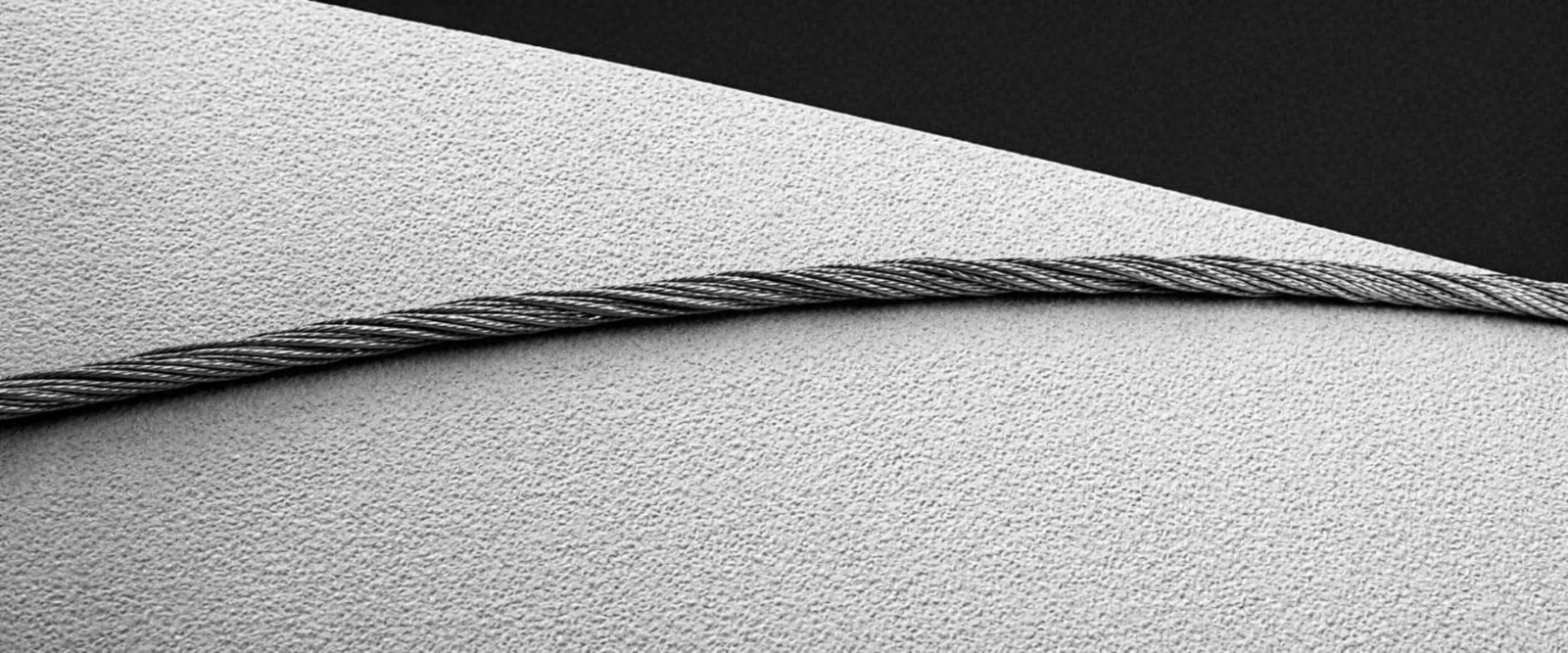
Ceramic Disc Supply Backed by Practical Texturing Expertise
TSP supplies ceramic discs with practical application support to match the dimensions, profile and surface specification to your friction unit and yarn. Our support draws on Bipin Chauhan’s texturing experience since 1986, covering disc selection, production trials and process troubleshooting.
Ceramic Disc Types
Working Disc
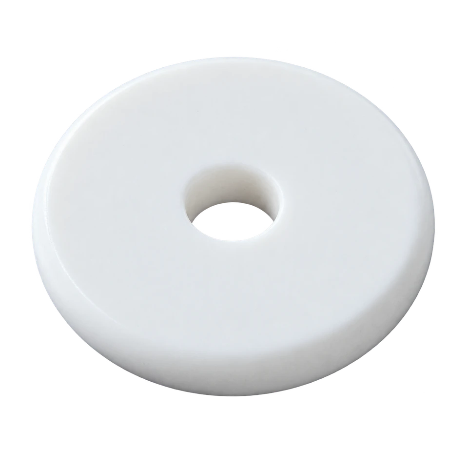
Working Surface for Twist Generation
Guide Disc
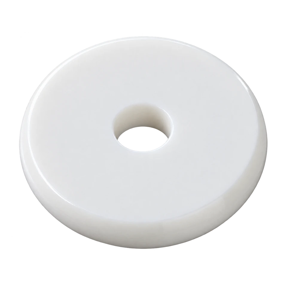
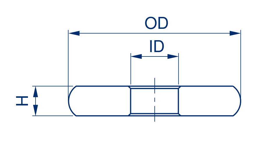
Plain Symmetric Edge Polished Guide Disc
Profiled Guide Disc
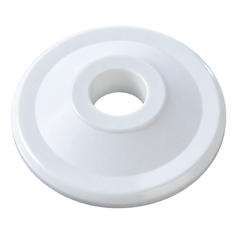

Polished Reduced Edge Profile Exit Disc
Knife Edge Disc
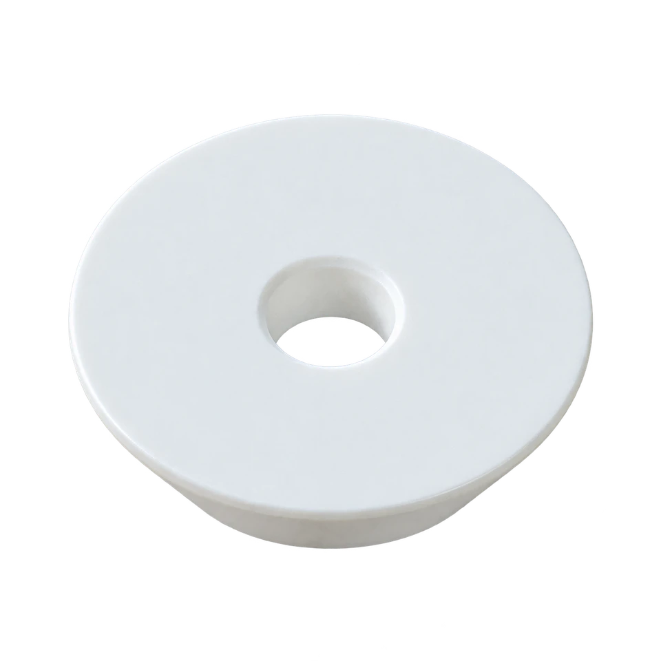
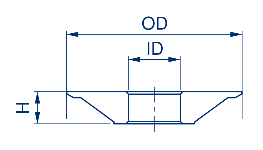
Polished Knife Edge Profile Exit Disc
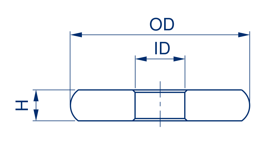
OD = outside diameter | ID = bore diameter | H = thickness. Confirm the complete drawing and working surface grade before ordering.
Disc Sizes and References
All dimensions are in millimetres. Quote the disc family and reference together, along with OD, ID, H and profile. References are local to each table and are not OEM part numbers.
Working Discs
| Reference | OD (mm) | ID (mm) | H (mm) | Photo |
|---|---|---|---|---|
| 1 | 58 | 14.45 | 9 | A |
| 2 | 54.5 | 12 | 9 | A |
| 3 | 52 | 14.45 | 9 | A |
| 4 | 52 | 12 | 9 | A |
| 5 | 49.6 | 12 | 6 | A |
| 6 | 45 | 12 | 6 | A |
Guide Discs
| Reference | OD (mm) | ID (mm) | H (mm) | Photo |
|---|---|---|---|---|
| 1 | 58 | 14.45 | 9 | B |
| 2 | 52 | 14.45 | 9 | C |
| 3 | 52 | 12 | 6 | B |
| 4 | 47.8 | 12 | 6 | C |
| 5 | 52 | 14.45 | 9 | B |
| 6 | 46 | 14.45 | 9 | C |
| 7 | 52 | 12 | 9 | B |
| 8 | 46 | 12 | 9 | C |
| 9 | 49.6 | 12 | 6 | B |
| 10 | 45 | 12 | 6 | B |
Knife Edge Discs
| Reference | OD (mm) | ID (mm) | H (mm) | Photo |
|---|---|---|---|---|
| 1 | 54.5 | 14.45 | 9 | D |
| 2 | 49 | 14.45 | 9 | D |
| 3 | 49 | 12 | 9 | D |
| 4 | 48 | 12 | 6 | D |
| 5 | 47.2 | 12 | 6 | D |
| 6 | 43 | 12 | 6 | D |
Ceramic Disc Selection Table
Disc Combination by Yarn Linear Density
| Disc Thickness | Disc Combination | Yarn Linear Density (Denier) | |||||||
|---|---|---|---|---|---|---|---|---|---|
| 20 | 30 | 40 | 50 | 70 | 100 | 150 | 300 | ||
| 6mm | 1 / 3 / 1 | ● | ● | Not Indicated | Not Indicated | Not Indicated | Not Indicated | Not Indicated | Not Indicated |
| 6mm | 1 / 4 / 1 | Not Indicated | ● | ● | ● | ● | Not Indicated | Not Indicated | Not Indicated |
| 6mm | 1 / 5 / 1 | Not Indicated | Not Indicated | ● | ● | ● | Not Indicated | Not Indicated | Not Indicated |
| 6mm | 1 / 6 / 1 | Not Indicated | Not Indicated | Not Indicated | ● | ● | ● | Not Indicated | Not Indicated |
| 6mm | 1 / 7 / 1 | Not Indicated | Not Indicated | Not Indicated | Not Indicated | ● | ● | ● | Not Indicated |
| 9mm | 1 / 4 / 1 | Not Indicated | Not Indicated | ● | ● | ● | Not Indicated | Not Indicated | Not Indicated |
| 9mm | 1 / 5 / 1 | Not Indicated | Not Indicated | Not Indicated | Not Indicated | ● | ● | ● | Not Indicated |
| 9mm | 1 / 6 / 1 | Not Indicated | Not Indicated | Not Indicated | Not Indicated | Not Indicated | ● | ● | Not Indicated |
| 9mm | 1 / 7 / 1 | Not Indicated | Not Indicated | Not Indicated | Not Indicated | Not Indicated | Not Indicated | ● | ● |
| 9mm | 1 / 8 / 1 | Not Indicated | Not Indicated | Not Indicated | Not Indicated | Not Indicated | Not Indicated | ● | ● |
A dot marks a selection shown in the table. Confirm the final disc combination for your yarn and friction unit with TSP.
Selecting the Disc for Your Application
Disc Selection and Supply
Review the existing part number or drawing and specify the required dimensions, edge profile and working surface.
Application Support
Consider yarn construction, filament fineness, processing speed, disc configuration and yarn tensions when selecting a disc.
Process Troubleshooting
Investigate filament damage, unstable tension, deposits and inconsistent yarn properties across the complete yarn path.
Production Evaluation
Help define a practical comparison using yarn quality, disc condition, cleaning needs and service life.
Our selection process focuses on consistent crimp and tensile properties, controlled filament damage, stable yarn transport and practical maintenance. Evaluate disc value through service life and operating cost as well as purchase price. The appropriate grade and operating conditions determine the result.
Working Edge Geometry and Yarn Contact
The outside diameter, thickness and bore identify the principal dimensions. The edge profile and radius define the yarn contact geometry.
The working edge controls the contact geometry between disc and yarn. Surface topography influences grip and sliding at that contact. Both affect twist transmission, yarn transport and the stresses experienced by individual filaments.
Rounded Working Edge
The rounded profile provides a curved yarn contact surface for general purpose applications. Select the radius and surface grade to suit the yarn and friction unit.

Flatter Working Edge
The flatter profile provides a broader yarn contact region and can be evaluated for sensitive or fine filament yarns. Any improvement in tension, filament damage or yarn strength must be confirmed under the intended operating conditions.

These profiles are schematic and have no specified dimensions. Confirm the actual edge radius, drawing, part number and surface grade. These working edge examples are separate from catalogue profile letters A–D above; an illustration alone does not establish dimensional equivalence or a predictable performance difference.
A broader contact region may redistribute local pressure, but its effect depends on the complete geometry and surface. A flatter edge does not automatically reduce yarn tension, filament debris or strength loss. Check these effects by measuring yarn properties and production stability under the intended operating conditions.
Working Surface Selection
The selection objective is sufficient twist transfer with limited filament damage. The matrix links these two production outcomes to the checks needed when evaluating a disc and its operating conditions.
Selection Objective
Higher twist transfer | Lower filament damage
Sufficient twist transfer with limited filament damage.
Review Contact Conditions
Higher twist transfer | Higher filament damage
Twist transfer is achieved, but filament damage is excessive.
Improve Twist Transfer
Lower twist transfer | Lower filament damage
Check the surface grade, contact geometry and operating settings.
Review the Complete Process
Lower twist transfer | Higher filament damage
Twist transfer is insufficient and filament damage is excessive.
Working Surface Suitability
A surface must provide the contact conditions needed for the application.
A polished guide surface is not automatically suitable for a working disc.
Roughness and Performance
Equally, a higher roughness value does not by itself establish stronger twist insertion or greater filament damage.
Arithmetical Mean Roughness (Ra)
Ra is one measure of surface roughness. It does not fully describe peak shape, spacing or the way a finished yarn interacts with the surface.
Yarn guide surfaces with similar Ra values can have different friction coefficients.
Guide surface behaviour should not be used as a direct measure of working disc performance.
Grade Selection
Select a defined working surface grade and assess it with the chosen edge geometry, spin finish, yarn and machine settings.
The practical objective is stable processing with the required yarn properties throughout the operating and cleaning cycle.
Application Checks
Specify the finish and grade for the yarn and friction unit, including fine filament applications.
Check twist stability, yarn transport, tensions, crimp and broken filaments.
A smooth guide surface alone does not establish suitability for a working disc.
Deposits and Surface Changes
If deposits or visible surface changes are present, inspect and clean before assessing the underlying grade. Check recovery after cleaning and how quickly deposits return.
Grooved surfaces may be evaluated for spun dyed yarn applications where deposit accumulation is a concern.
Contamination and Cleaning
Recognising Contamination
Spin finish residues, polymer deposits and additives from dope dyed yarns can contribute to surface contamination. Inspect discs when deposits, slippage, unstable tension or increased broken filaments appear. A shiny or glazed appearance alone does not distinguish removable contamination from a permanent surface change.
Choosing a Cleaning Method
Record the surface condition and follow the approved cleaning procedure for the actual disc. Ultrasonic cleaning with a compatible agent is one option. Chemical or thermal methods may also be suitable for some solid ceramic discs. Confirm compatibility with the complete component, including any hub, coating or adhesive.
Refitting and Disc Condition
Rinse, dry and inspect as specified before refitting. Avoid unapproved abrasive polishing, which can alter the working surface. Cleaning does not repair chipped edges or restore an out of specification profile.
Yarn Quality and Tension Diagnosis
T1 and T2 Tension
T1 denotes yarn tension before the friction unit and T2 denotes tension after it. Record sensor locations because machine terminology can differ. A change in T2 is a diagnostic signal, not proof of disc contamination. Check the yarn lot, operating settings, yarn path, discs and friction unit together.
Shade Variation and Intermingling
Investigate shade variation across feed yarn quality and the complete thermal and mechanical process. Assess intermingling separately against the jet’s operating and compressed air requirements. Disc topography or wet compressed air alone does not establish the cause of an intermingling defect.
PU and Ceramic Disc Performance Comparisons
Two polyester yarn trials compare polyurethane (PU) and ceramic discs under the conditions shown. These are individual reported examples, not performance guarantees. Tenacity is shown in cN/tex in the confirmed test units.
1 - 5 - 1 Disc Configuration
| Parameter | PU | Ceramic |
|---|---|---|
| Disc Configuration | 1 - 5 - 1 | 1 - 5 - 1 |
| Speed (m/min) | 650 | 700 |
| Tension Ratio | 0.70 | 0.90 |
| Elongation (%) | 20.6 | 20.4 |
| Tenacity (cN/tex) | 4.03 | 4.02 |
| Crimp Contraction (%) | 3.45 | 3.50 |
Higher speed with similar yarn properties.
1 - 6 - 1 Disc Configuration
| Parameter | PU | Ceramic |
|---|---|---|
| Disc Configuration | 1 - 6 - 1 | 1 - 6 - 1 |
| Speed (m/min) | 650 | 650 |
| Tension Ratio | 0.65 | 0.73 |
| Elongation (%) | 15.1 | 15.4 |
| Tenacity (cN/tex) | 3.10 | 3.14 |
| Crimp Contraction (%) | 7.40 | 7.40 |
Similar yarn properties. Longer ceramic service life was reported but not quantified.
Compare yarn properties, tension ratio, disc condition and service life together. Record how the tension ratio is calculated and where tensions are measured so trial results are interpreted consistently.
Evaluate Discs in Your Production
1. Record the Baseline
Record the current disc specification, service history, yarn lot, settings and baseline yarn properties. Agree acceptance limits before wider installation.
2. Compare Candidate Discs
Compare candidate discs on matched positions. Keep settings constant initially and record any later optimisation separately.
3. Measure Yarn Performance
Measure T1 and T2 variation, crimp contraction, tenacity, breaking elongation, broken filaments, deposits and end breaks using consistent sampling and measurement methods.
4. Confirm Consistency
Repeat the comparison over representative production and cleaning cycles. Check that any improvement is sustained across the required yarn properties and operating conditions.
Request Disc Selection and a Quotation
Send the information below so TSP can check suitability and recommend a specification:
Disc Identification
Disc family and catalogue reference, existing part number or drawing, OD, ID, H, edge profile and surface grade if known.
Machine and Friction Unit
Manufacturer, model and disc configuration.
Yarn and Process
Polymer, yarn count, filament count, dope dyed status, processing speed and operating settings.
Production Requirements
Current yarn properties, T1 and T2 measurements, contamination or filament damage, and the result you want to achieve.
Supply Requirements
Quantity and delivery destination.
Disc surface characteristics can be discussed as part of your enquiry. TSP can support specification review, supply and performance evaluation.
Wear Resistance
Ceramic contact surfaces support demanding continuous filament applications.
Controlled Yarn Path
Guide profiles help manage yarn contact, direction and tension.
Material Selection
Material and surface finish can be matched to the yarn and application.